Created on: December 2, 2022
Last updated: December 5, 2022
CONTENTS
1.1 Opening the Mercury Pro LTO
1.2 Removing the SAS Card
1.3 Removing the Existing Fans
1.4 Changing the 12VDC Power Cable
1.5 Adding the New Fans
1.6 Adding the SAS Card
1.7 Closing the Mercury Pro LTO
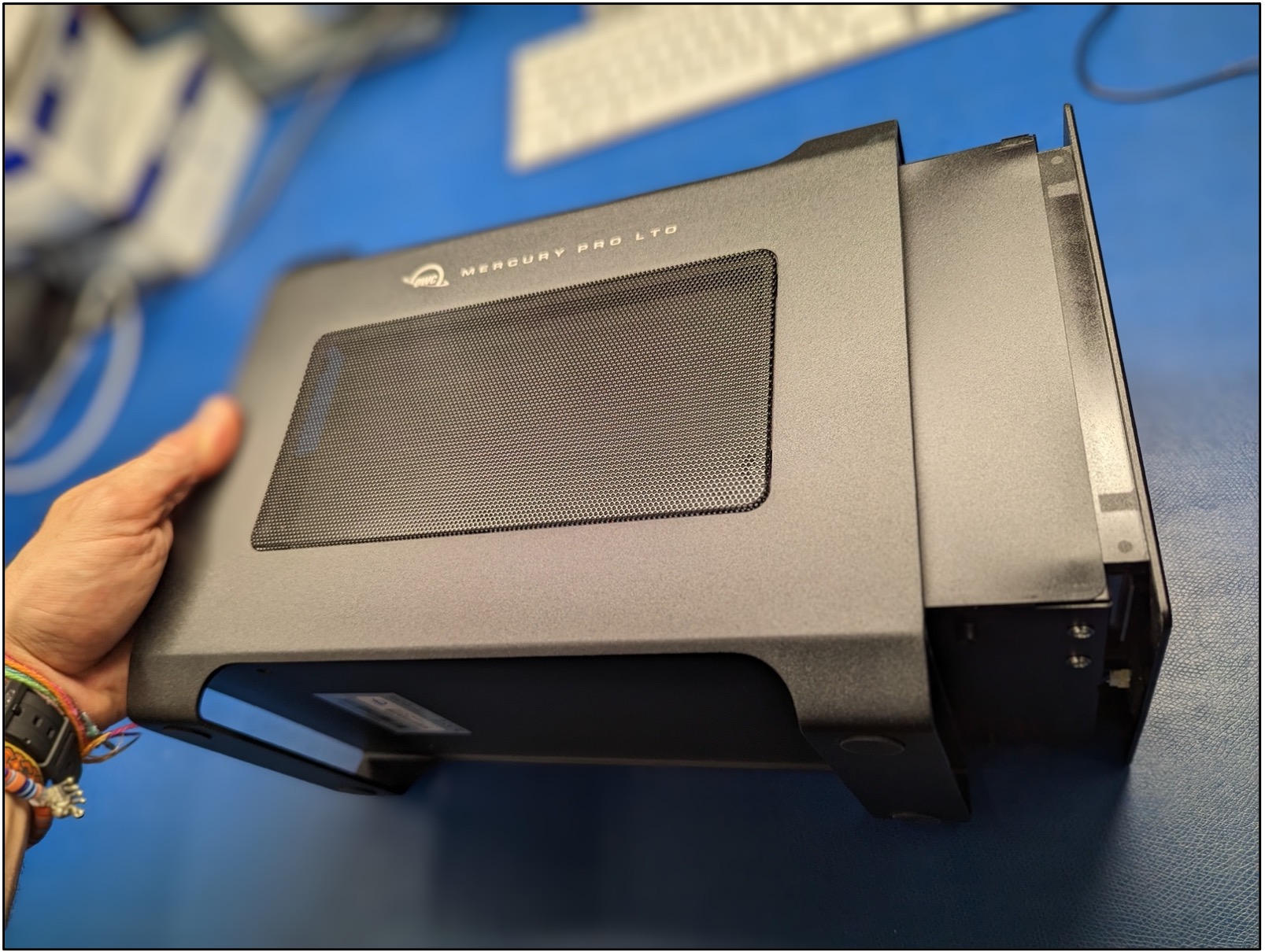
1.1 Opening the Mercury Pro LTO
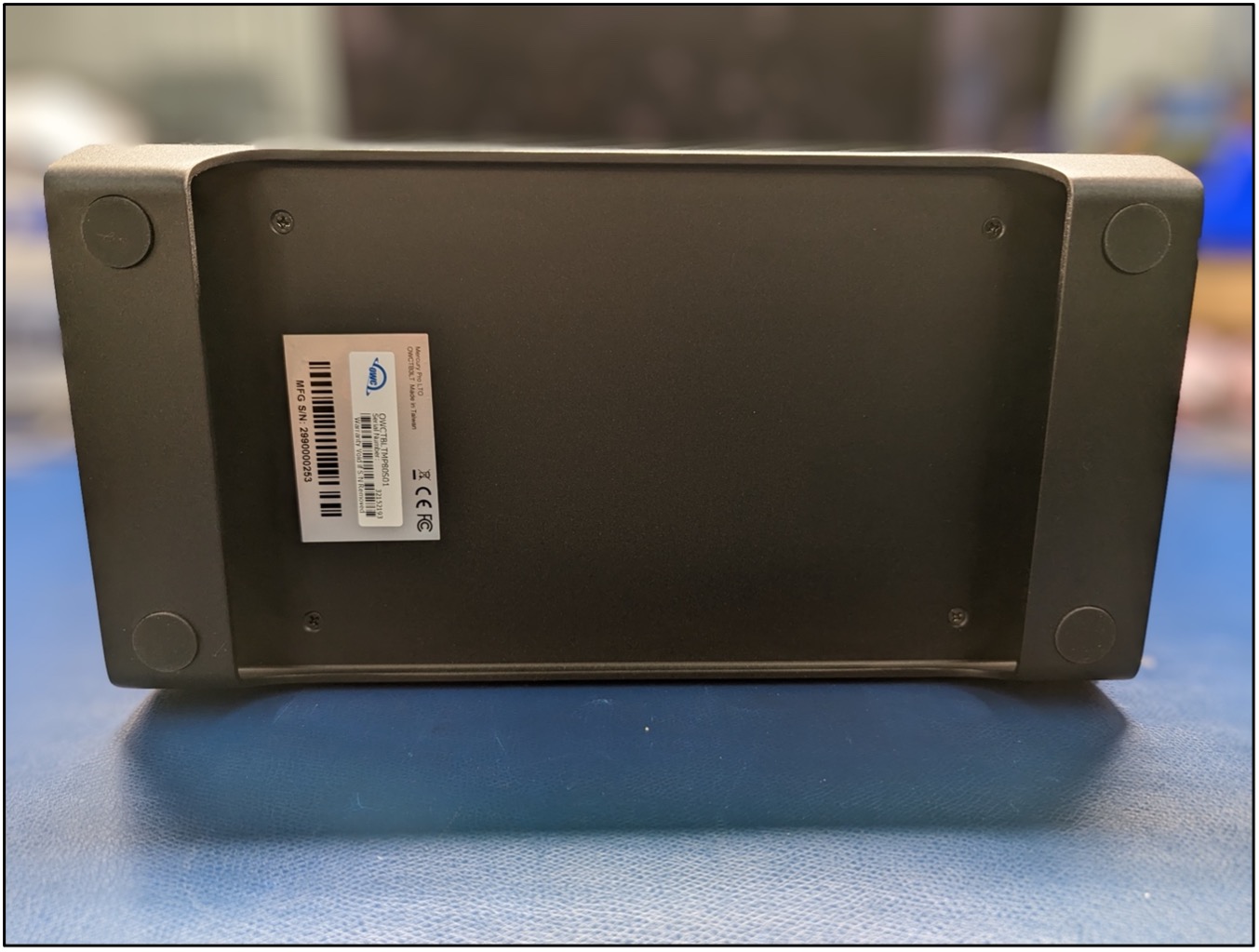
1. Carefully lay the LTO assembly on its side so the bottom is facing forwards exposing (4) chassis screws.
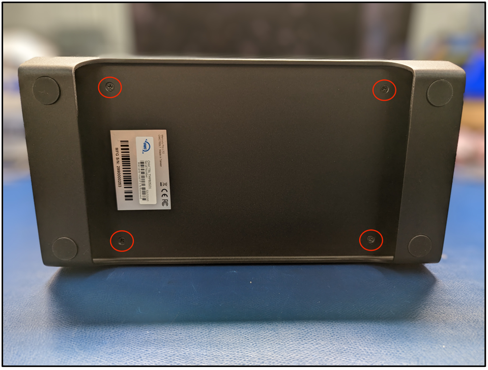
2. Obtain access to the inner chassis by removing the (4) chassis screws with a PH2 screwdriver. Store the screws for reassembly.
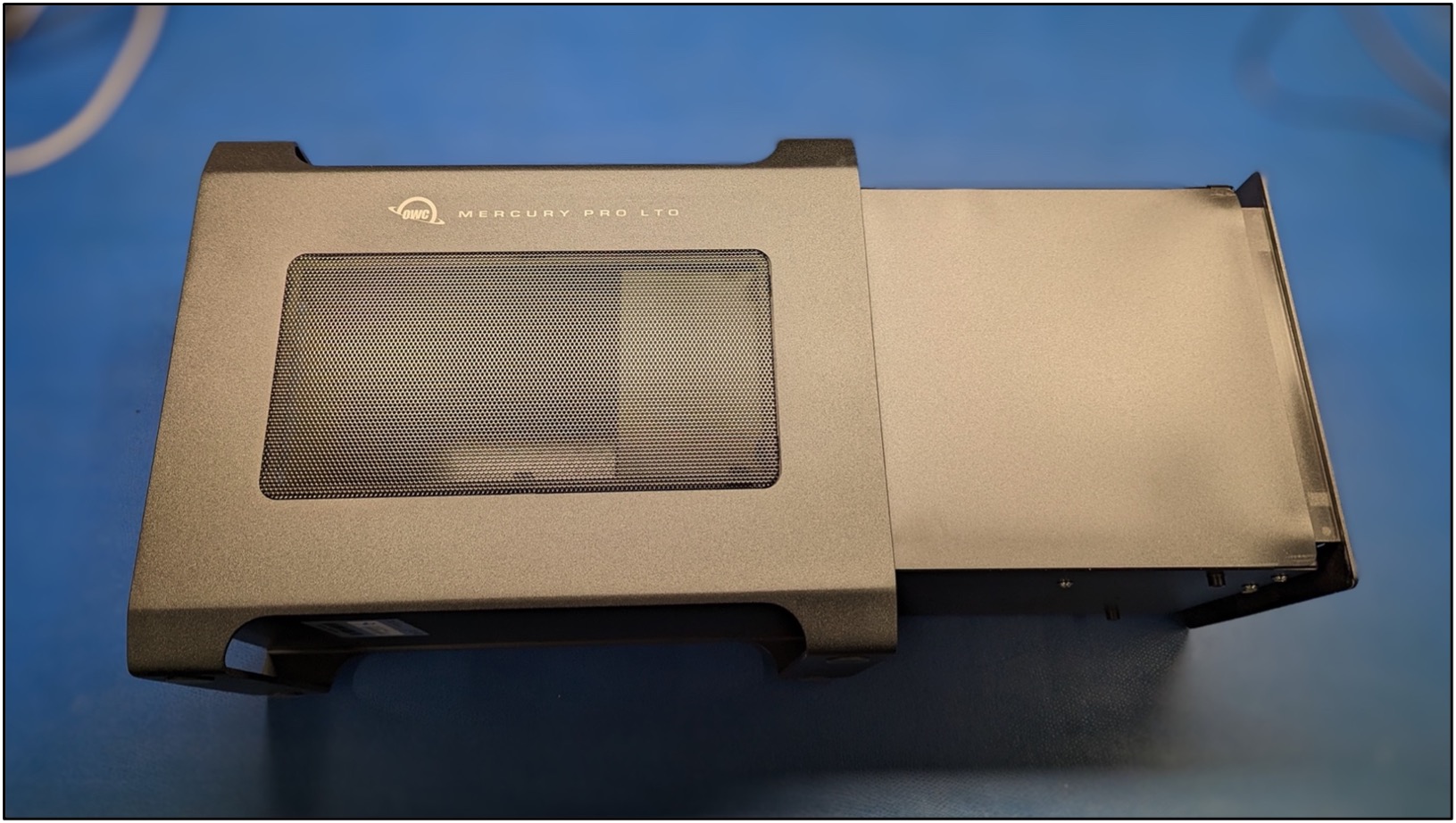
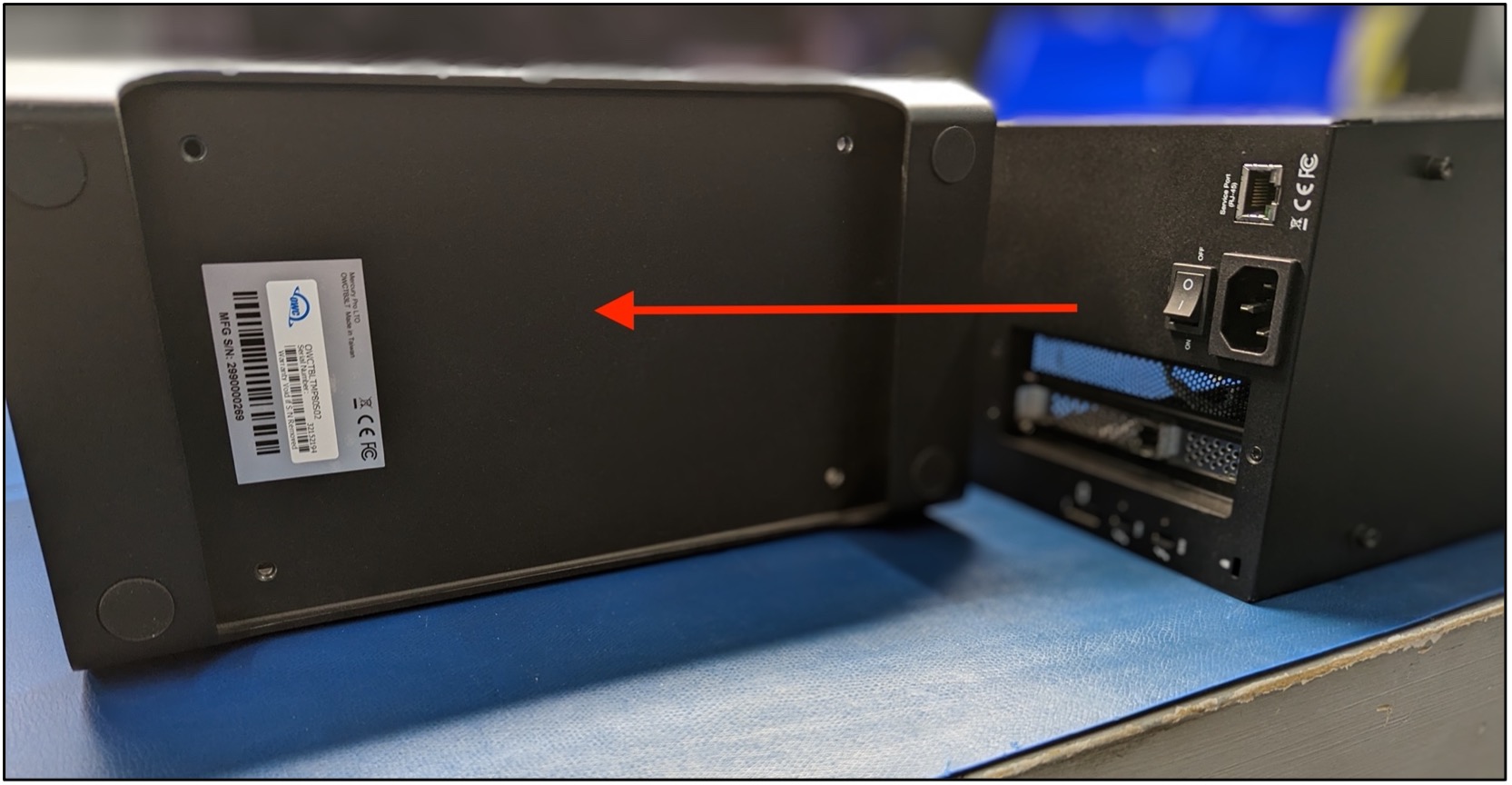
3. Pushing from the back of the LTO, slide the inner chassis out from the outer chassis. Store the outer chassis for reassembly.
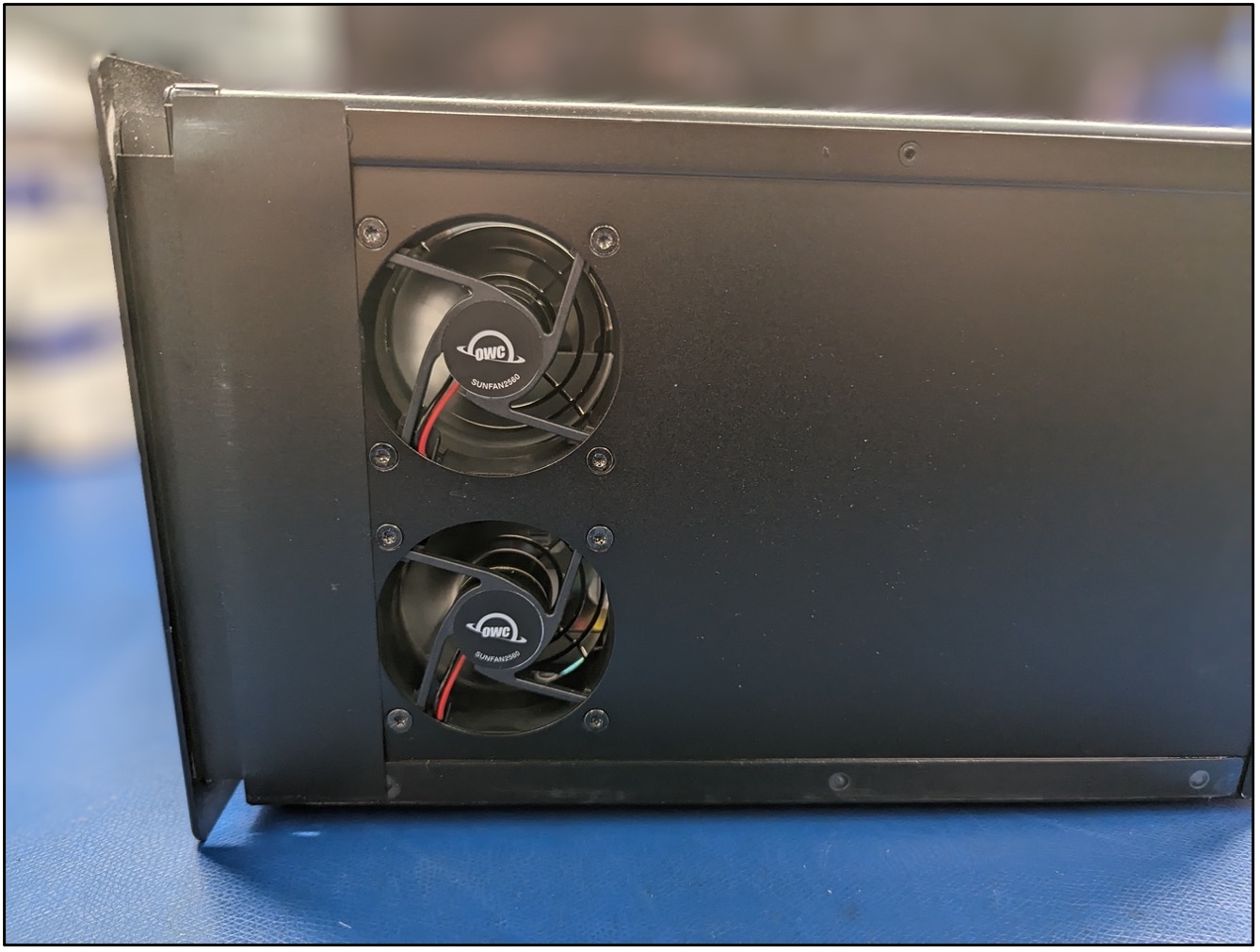
4. Stand the inner chassis upright allowing access to the components. Turn the inner chassis so the fan assemblies are facing forwards.
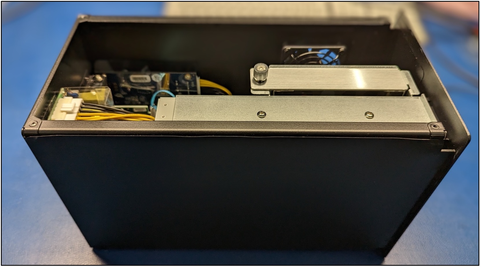
1.2 Removing the SAS Card
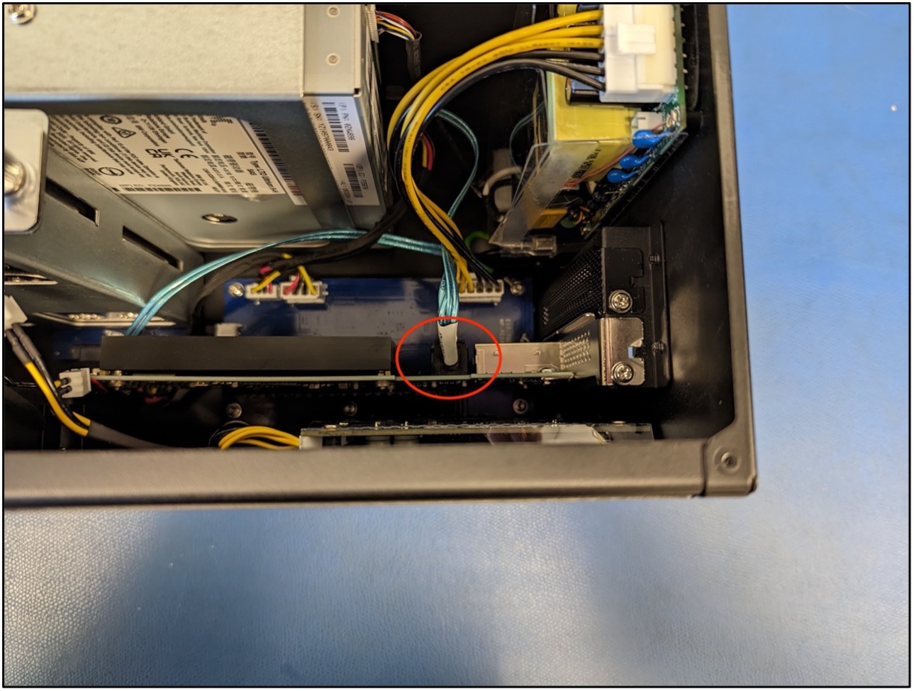
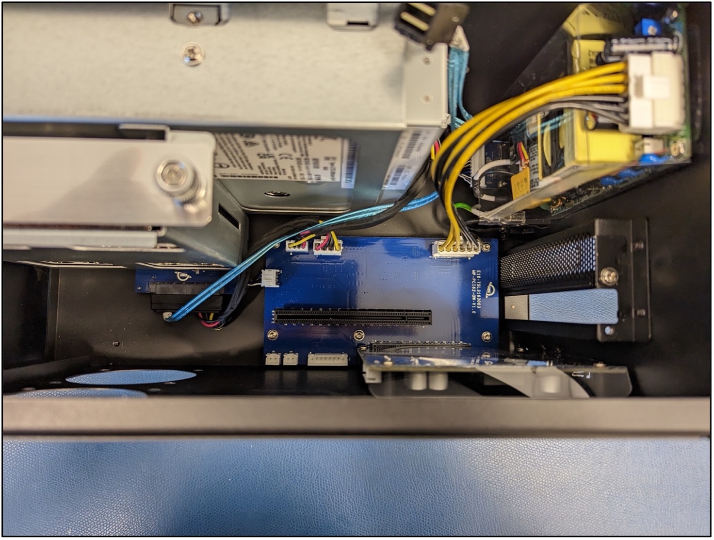
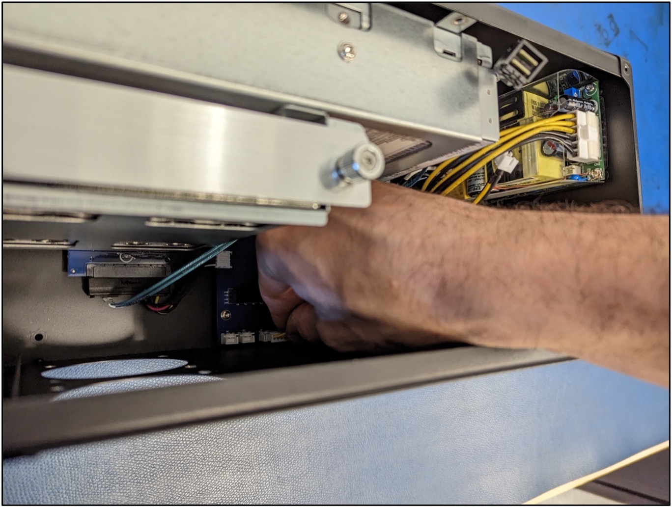
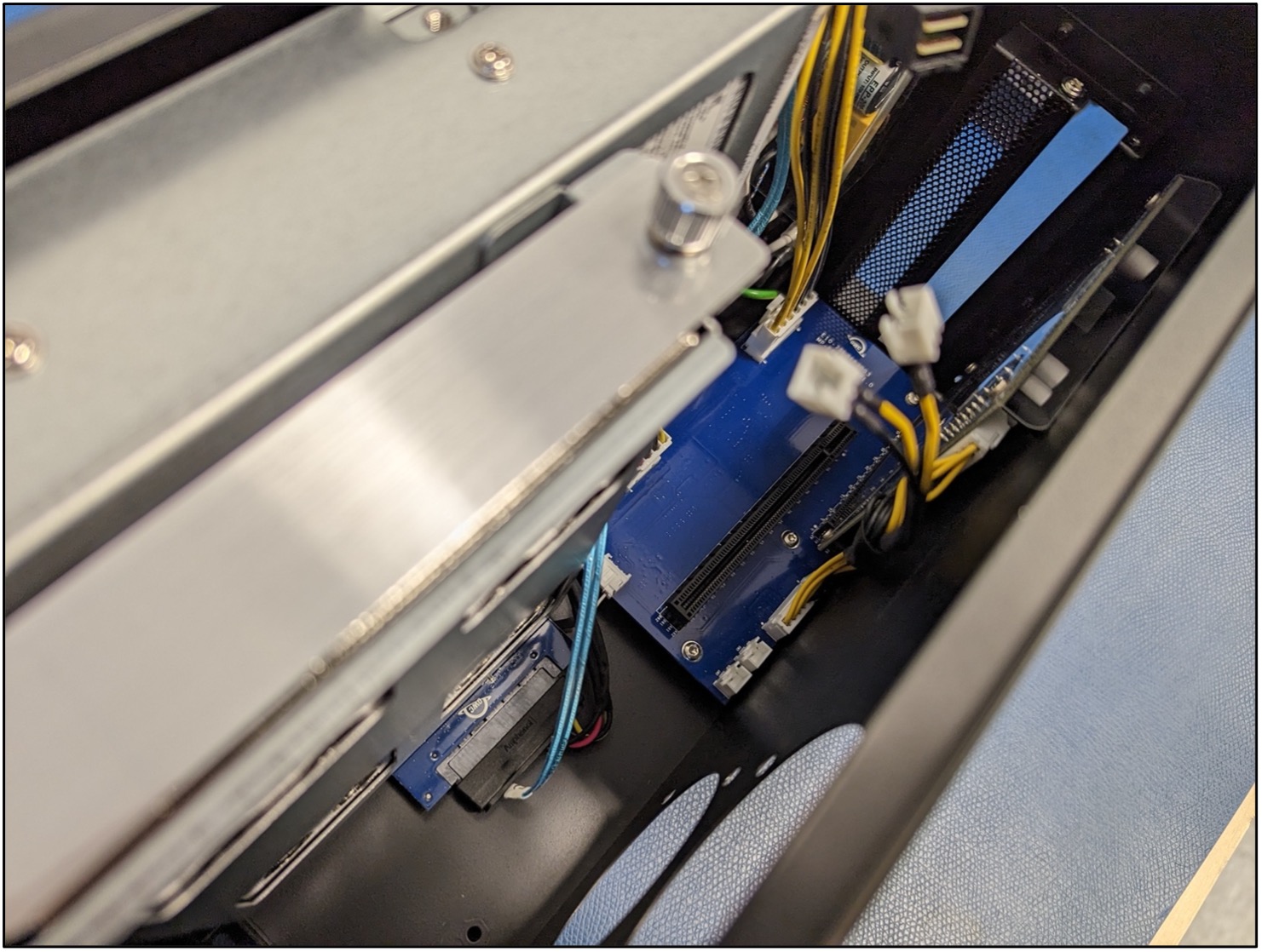
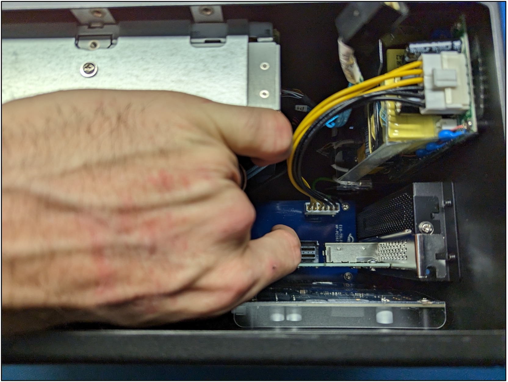
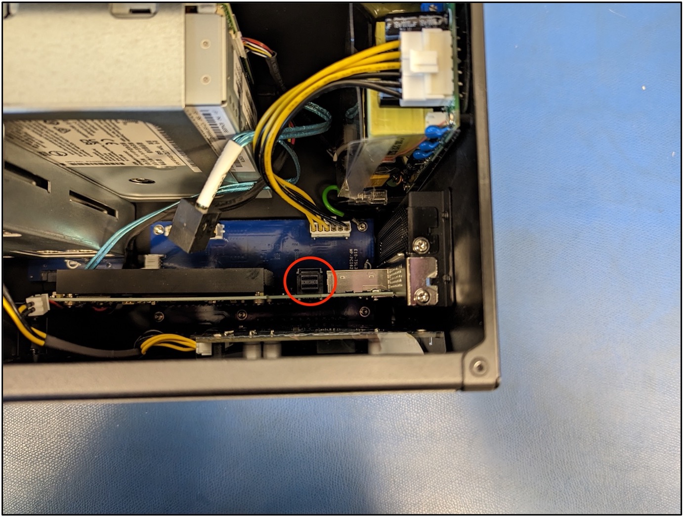
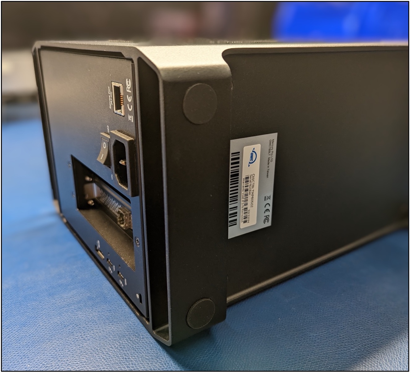
1. Removing the SAS card will allow easier access to the power connections on the Lower PCBa. Disconnect the SAS cable connected to the SAS card. Note: The cable connection has a press tab. Slightly pushing the tab while lifting up on the cable will disengage the connection.

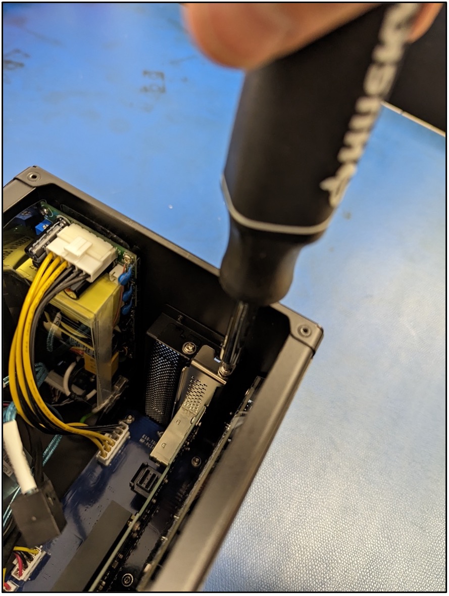
2. Remove the PCIe mounting bracket screw using a PH2 screwdriver. Store the screw for reassembly.
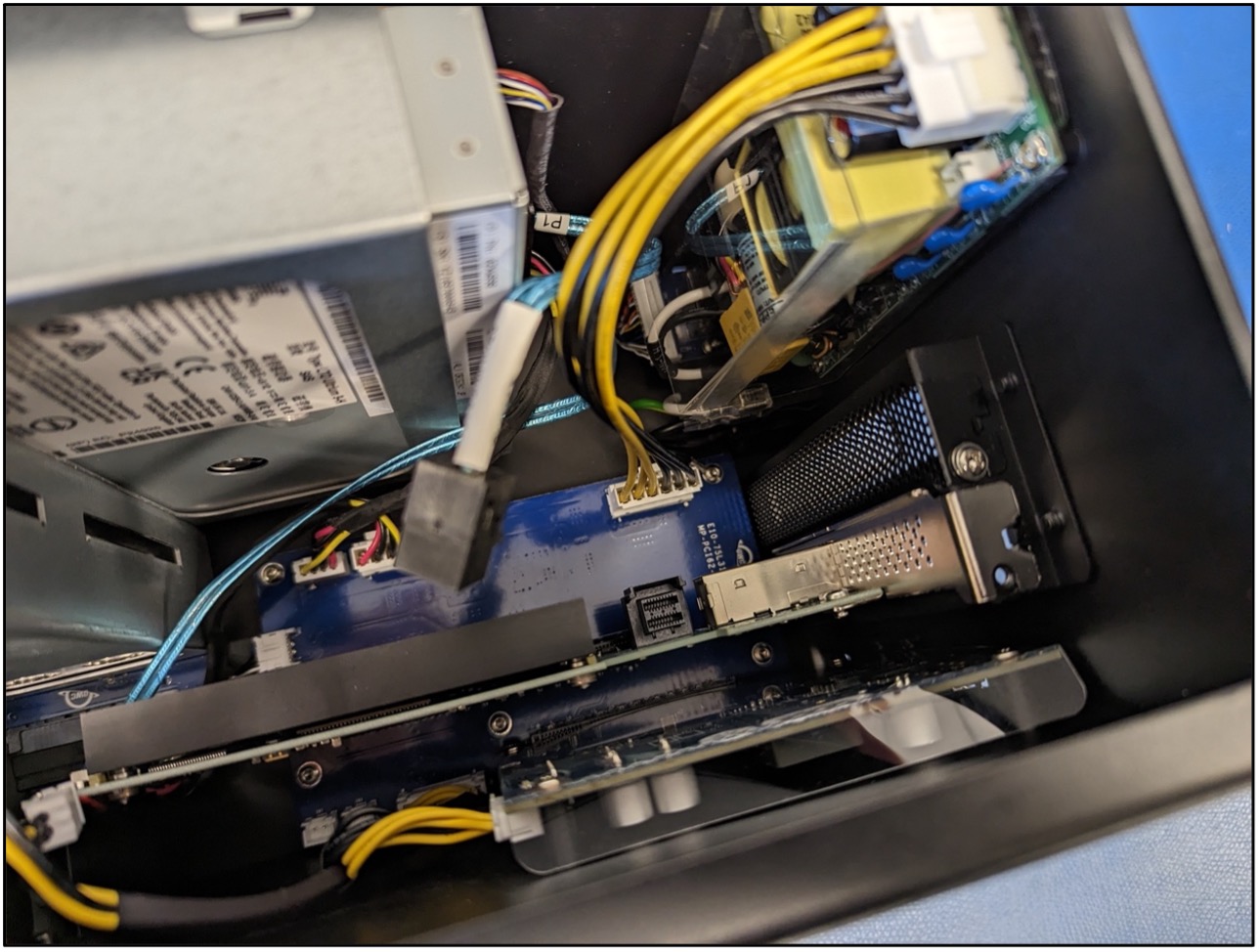
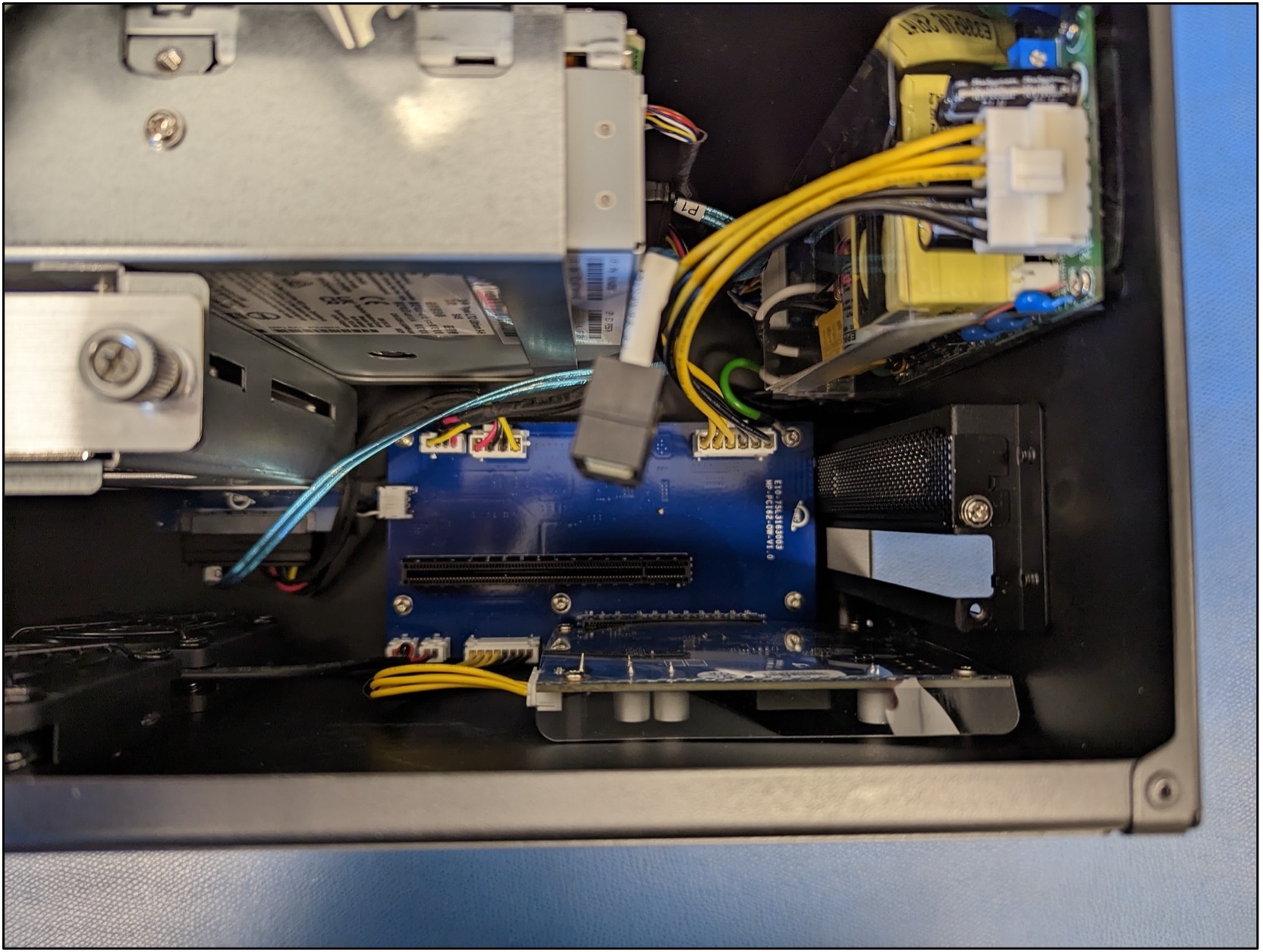
3. Carefully lift the card out of the inner chassis and store for reassembly.
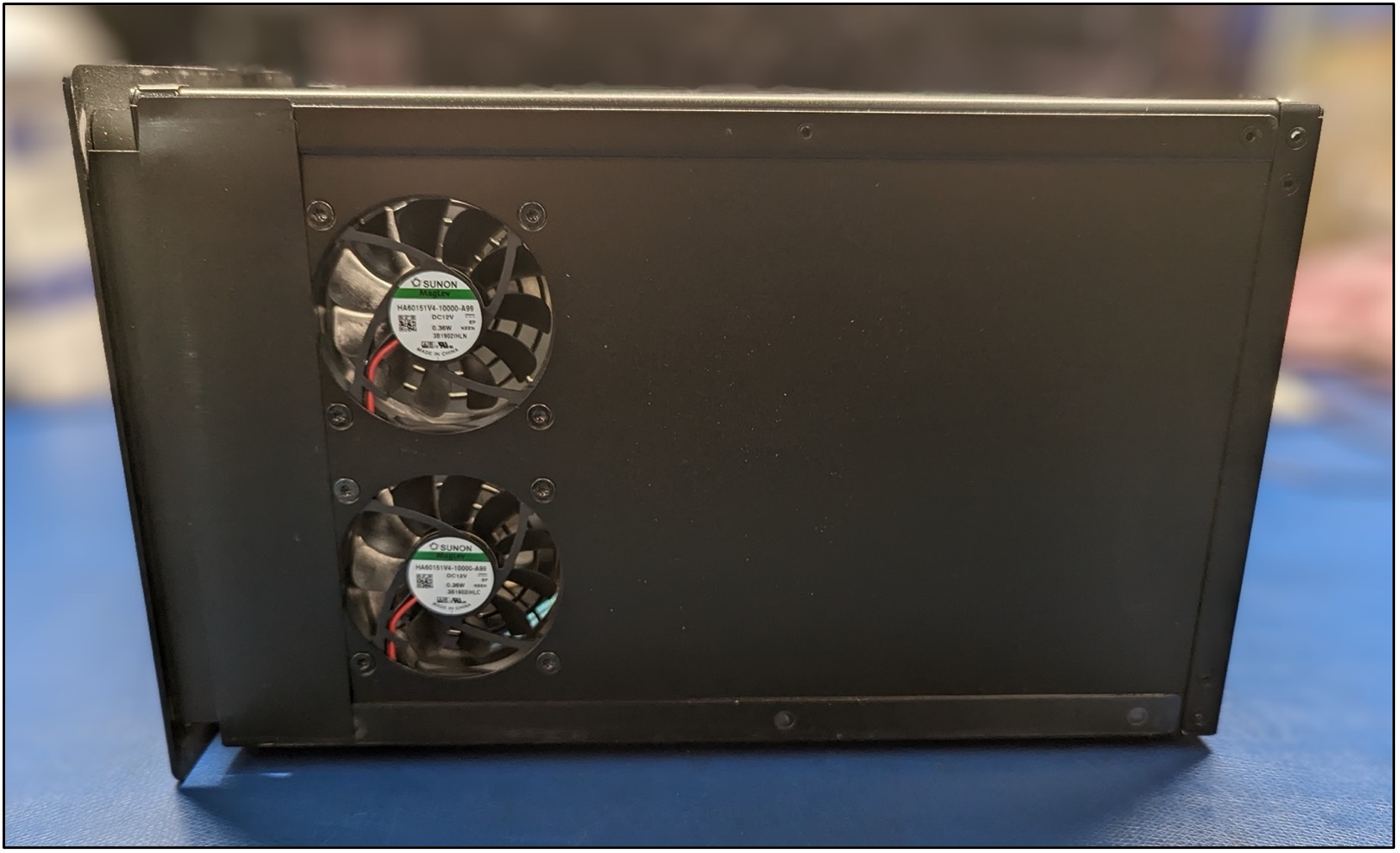
1.3 Removing the Existing Fans
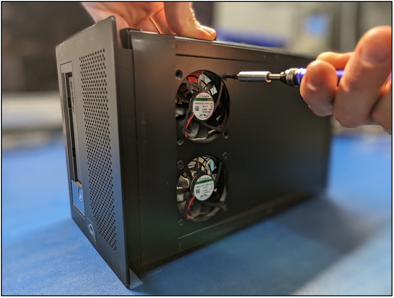
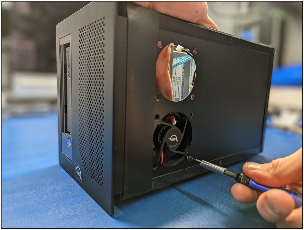
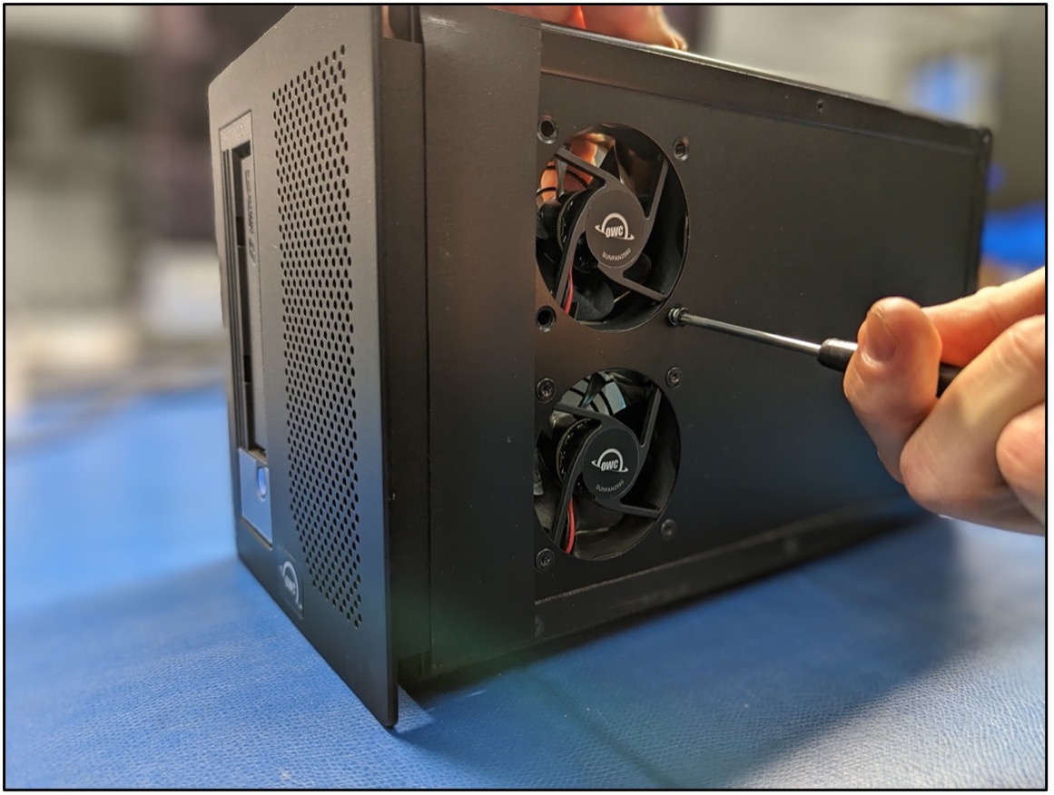
1. Starting with the upper fan, remove the (4) screws holding the fan assembly with a T10 screwdriver. Holding the back of the fan will help remove the last screw as the fan wants to move. Store the screws for reassembly. Note: The screw removal may feel tight. Slight pressure and a tight grip may be needed to unthread the screws.
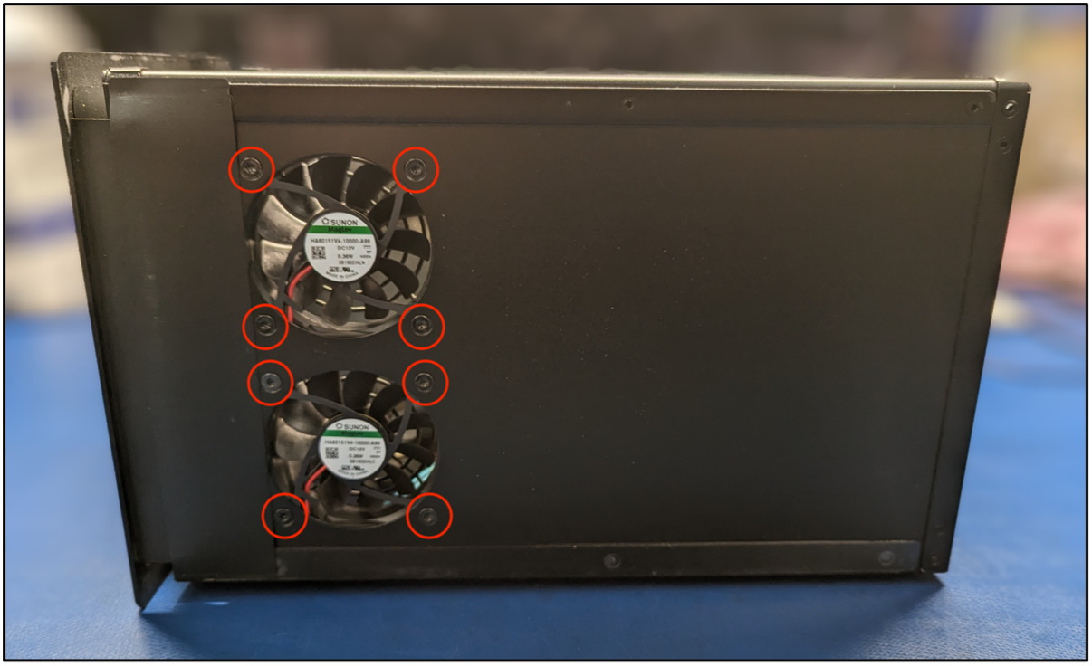
2. Move to the lower fan and remove the (4) screws holding the fan assembly with a T10 screwdriver. Store the screws for reassembly. The fans will now be loose in the chassis. Note: The screw removal may feel tight. Slight pressure and a tight grip may be needed to unthread the screws.

3. Once the fans are loose, disconnect the fan power connections from the Lower PCBa and remove the fans from the inner chassis.
4. Lay the fans on a flat surface and unfasten the blade shrouds from the original fans with a T10 screwdriver. Store the screws for reassembly of the blade shrouds on the new fans. Note: The screw removal may feel tight. Slight pressure may be needed to unthread the screws.
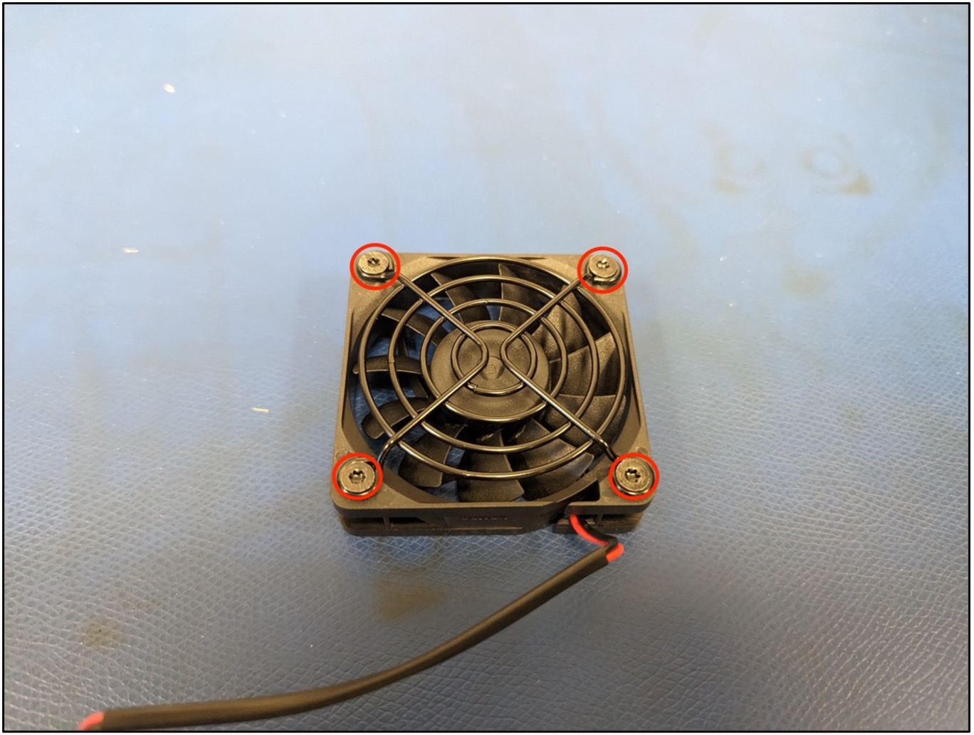
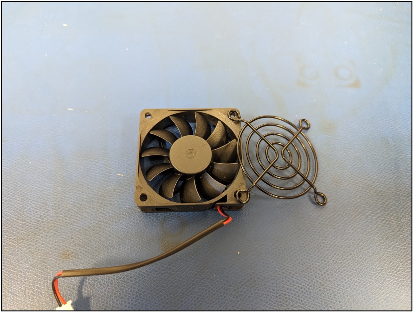
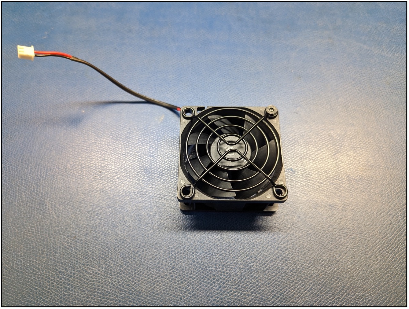
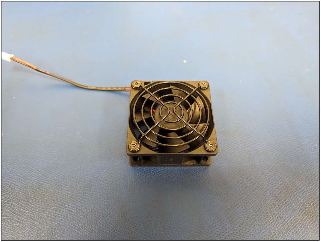
5. Lay the new fans on a flat surface with the OWC logo facing downwards. Fasten the blade shrouds to the new fans using the screws removed during disassembly with a T10 screwdriver. Store the new fans covered with blade shrouds for reassembly. Note: Partially threading the first screw will anchor the blade shroud while allowing for movement to help align the mounting holes.
1.4 Changing the 12VDC Power Cable
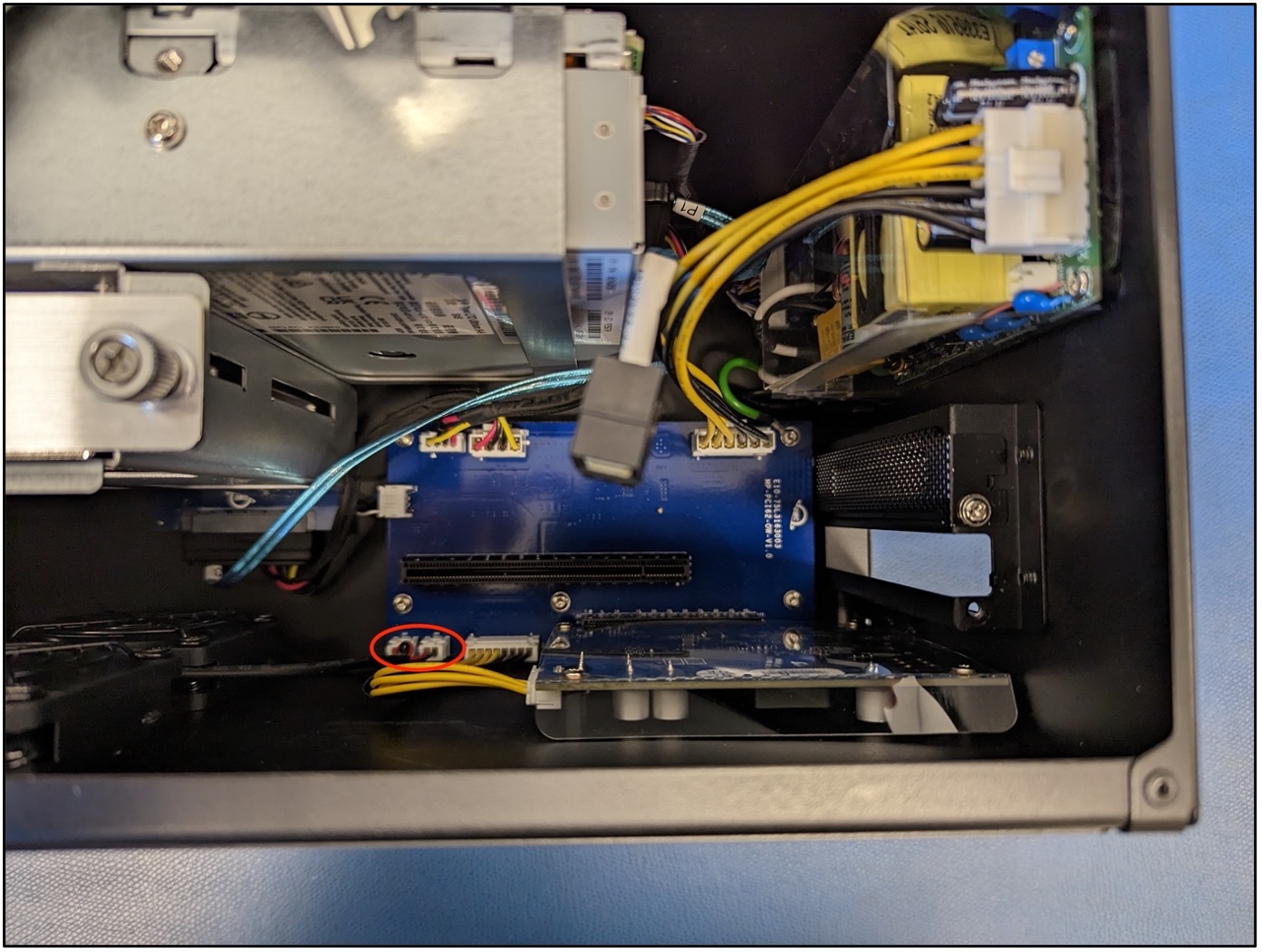
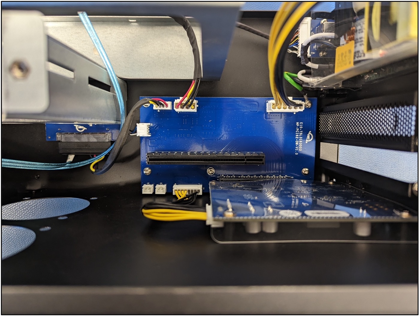
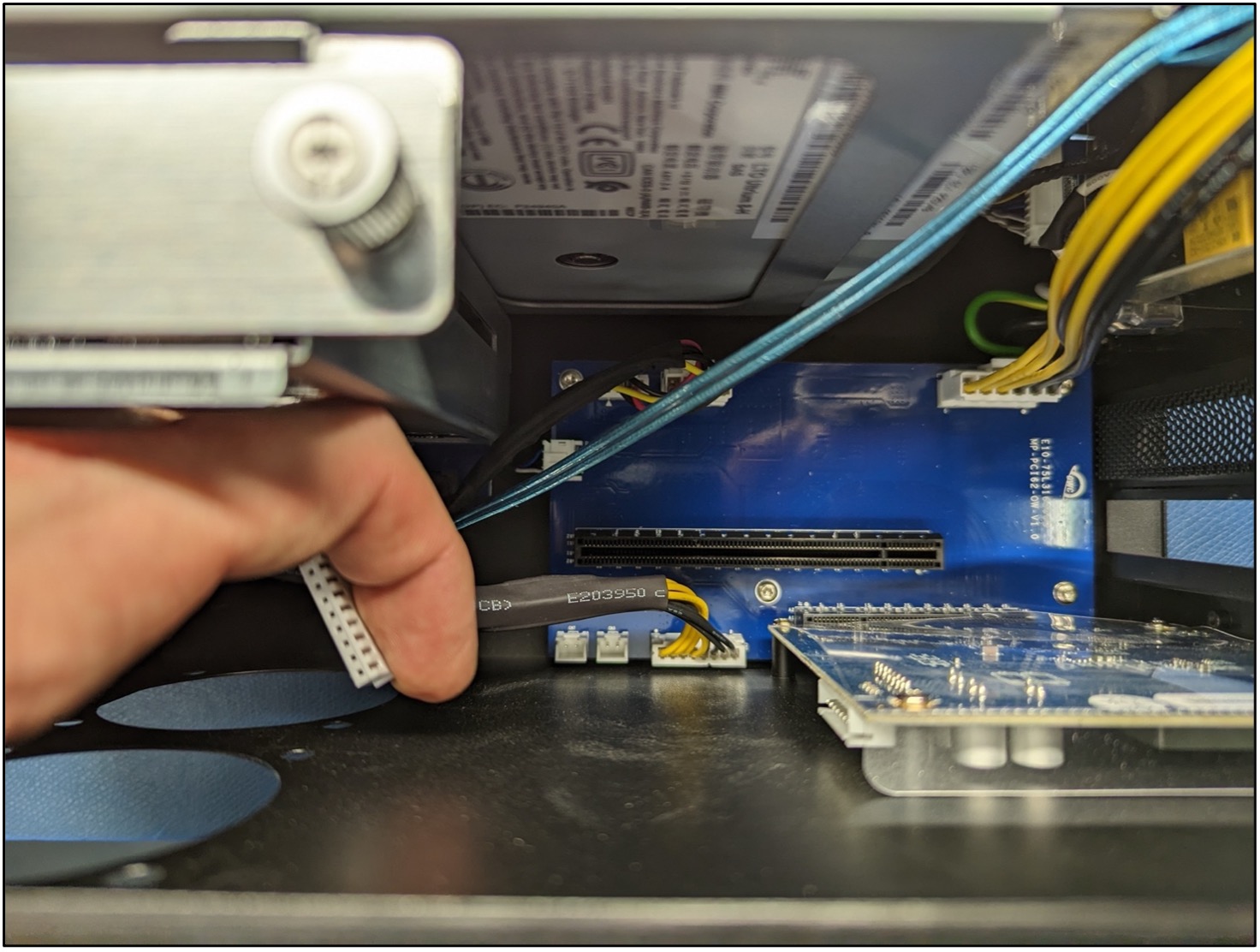
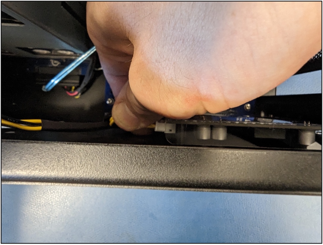
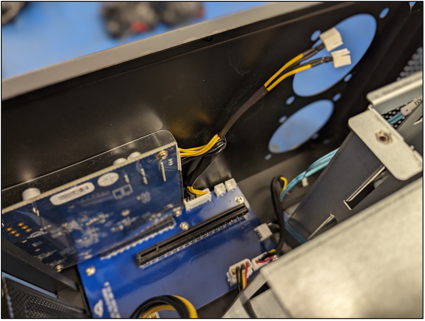
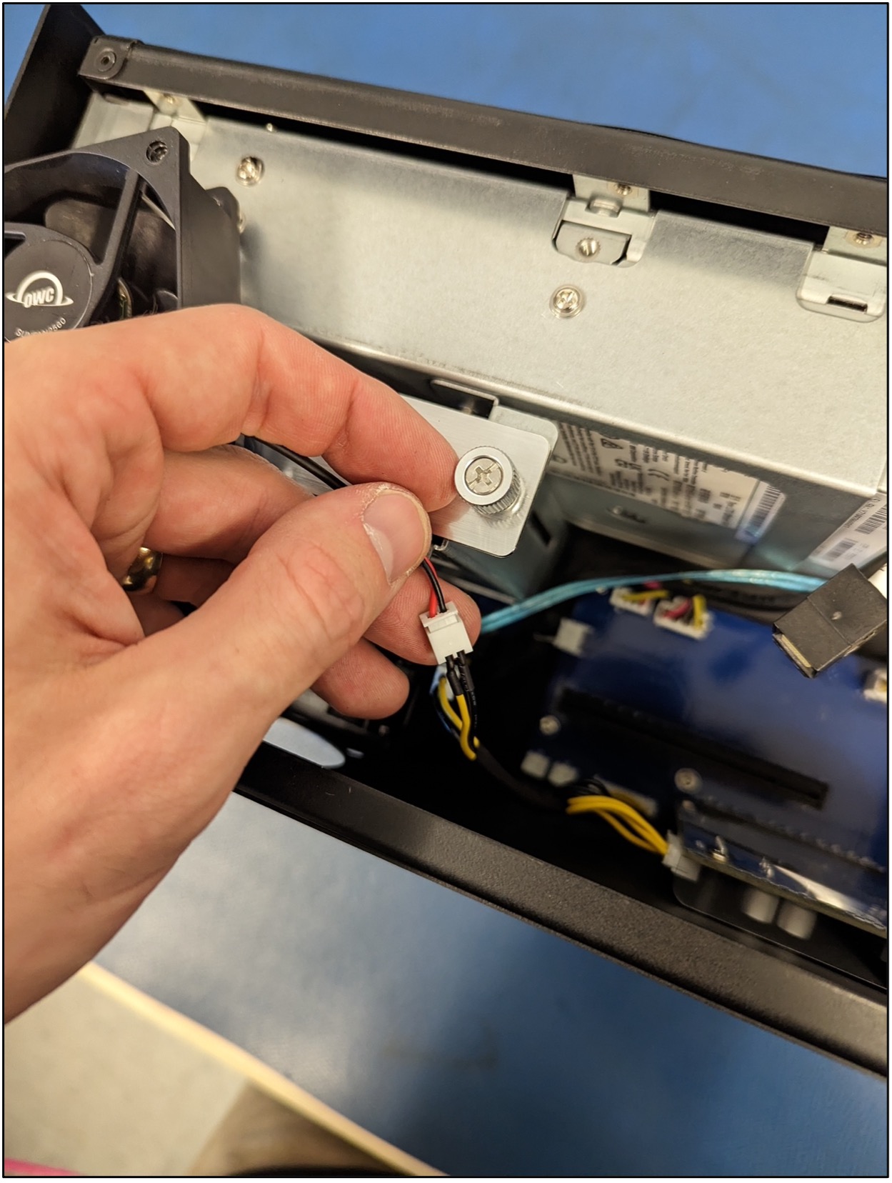
1. Disconnect both ends of the power cable connected from the Lower PCBa to the Thunderbolt I/O PCBa.
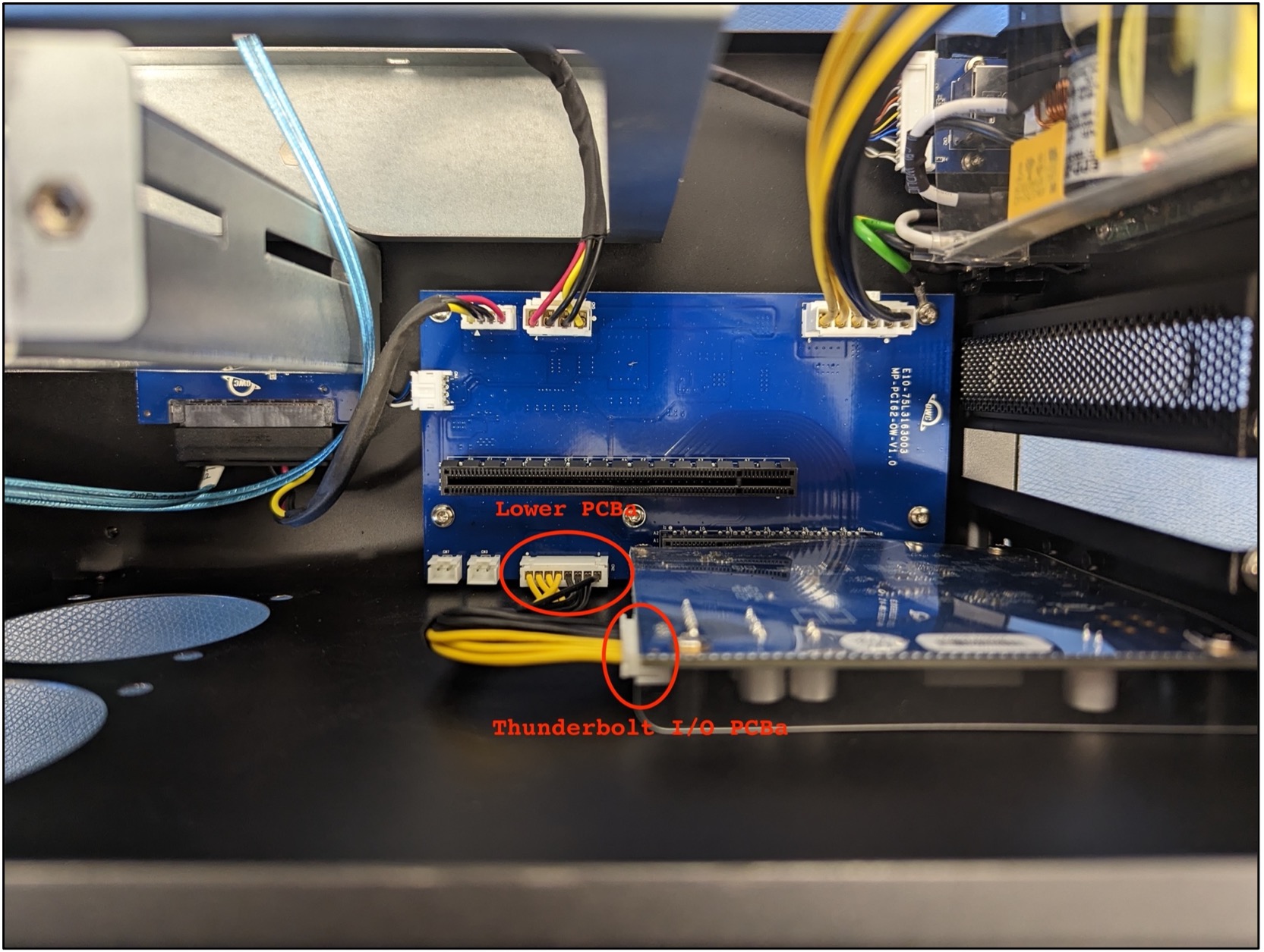
2. Connect the new cable by inserting the 8-pin end without the two 2-pin 12VDC extensions to the lower PCBa connector. Connect the other 8-pin end with the two 2-pin 12VDC extensions to the Thunderbolt PCBa. The two 2-pin 12VDC extensions will connect to the fans for supplying power.
1.5 Adding the New Fans
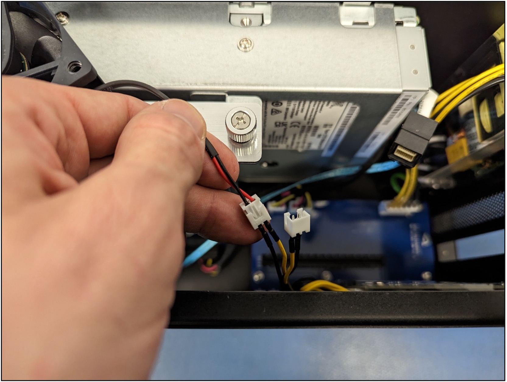
1. Starting with the lower fan, connect the fan power connection to one of the 2-pin 12VDC extensions.
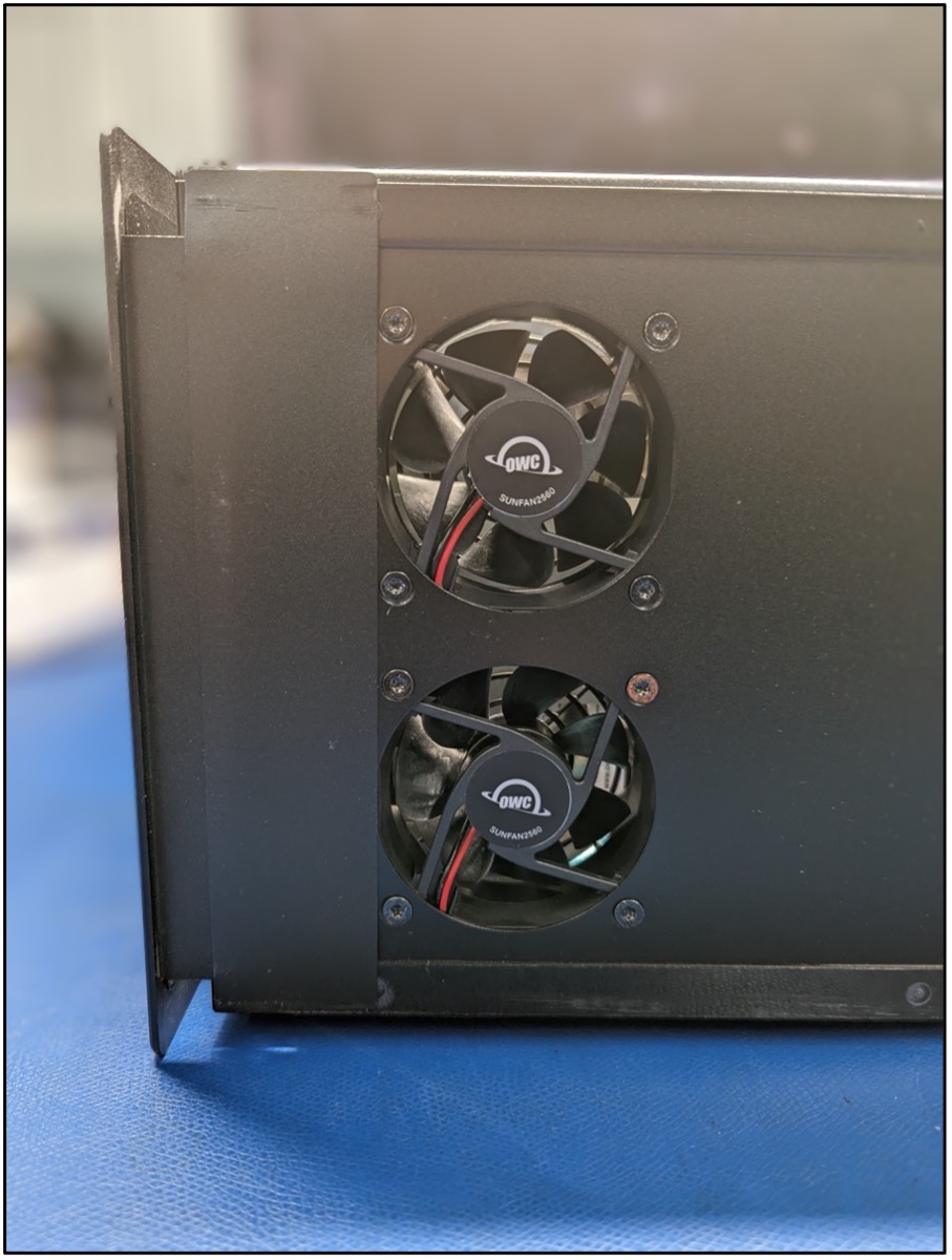
2. Position the fan into the inner chassis assembly with the OWC fan label (exhaust side) facing out and upright. Mount the fan using the screws removed during disassembly.

3. Moving to the upper fan, connect the fan power connection to the other 2-pin 12VDC extension.
4. Position the fan into the inner chassis assembly with the OWC fan label (exhaust side) facing out and upright. Mount the fan using the screws removed during disassembly.
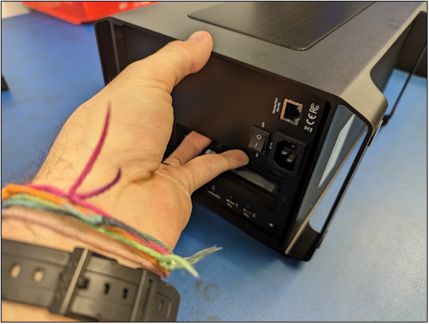
5. Connect the inner chassis using a 120VAC power cable to the power port of the inner chassis. Ensure the cable is connected to a power source.

6. Flip the power switch on the inner chassis to the on position, and the fans should begin blowing. If the fans are not receiving power, confirm all the swapped cables are completely and properly connected. Replacing the 12VDC power cable or the fans may be needed if the power isn’t restored after checking the swapped cable connections. Flip the power switch on the LTO inner chassis to the off position and disconnect the 120VAC power cable.

1.6 Adding the SAS Card
1. Carefully place the SAS card into the inner chassis. Align the connector on the card with the slot on the Lower PCBa. Carefully seat the card into the slot by gently pressing downwards. Note: If there is resistance, do not force the SAS card into the slot. Remove the card, re-align the connector, and try again.
2. Secure the SAS card with the PCIe mounting bracket screw used during disassembly with a PH2 screwdriver.


3. Reconnect the SAS cable to the SAS card. The press tab on the SAS cable will make a click sound once fully connected.

1.7 Closing the Mercury Pro LTO
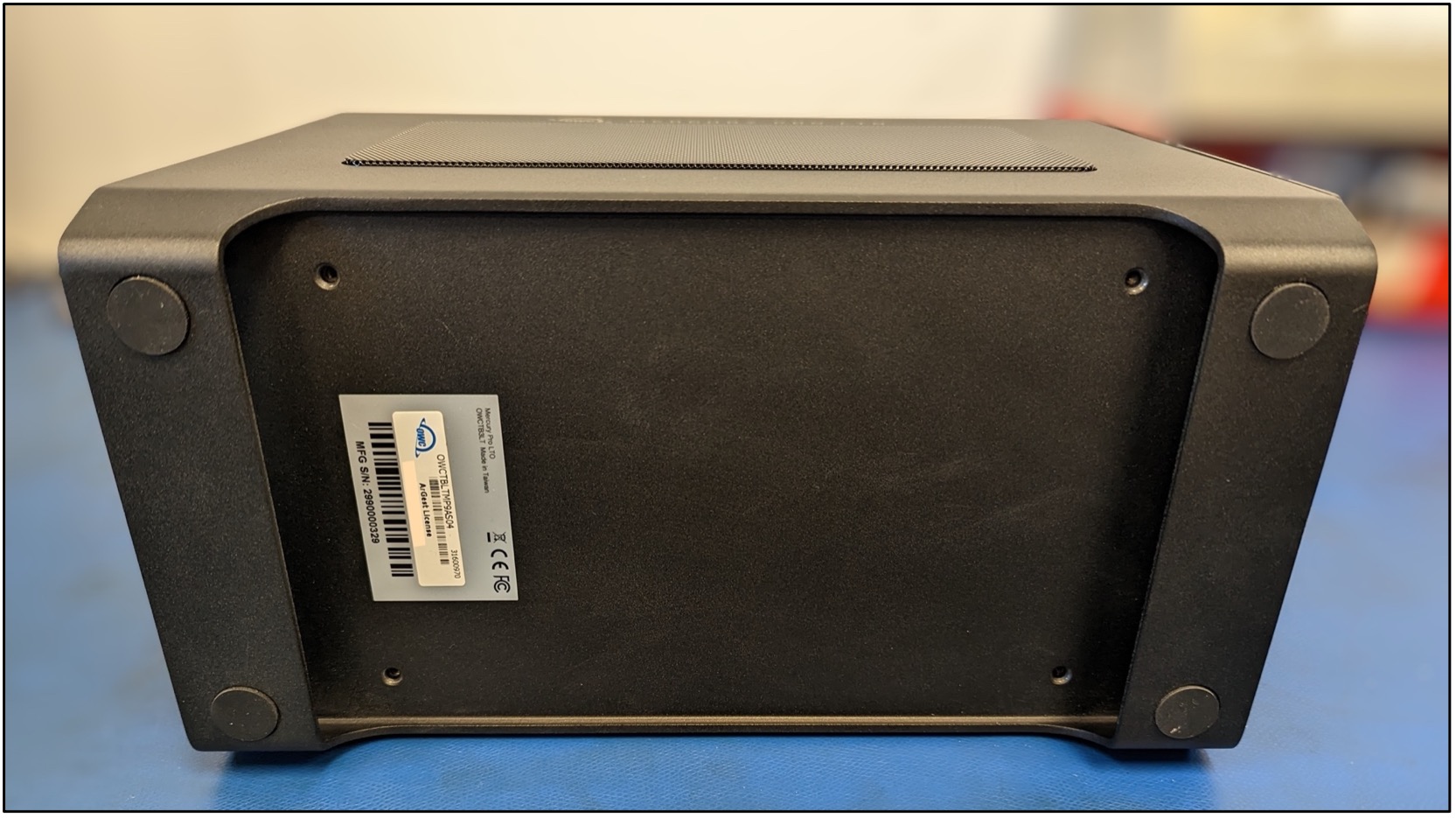
1. Carefully lay the outer chassis on its side so the bottom is facing forwards. Flip the inner chassis so the bottom is also facing forwards. Note: The back of the inner chassis needs to slide towards the MFG SN label on the outer chassis. The front of the inner chassis should be located away from the MFG SN label. The inner and outer chassis mounting holes will not align if the back of the inner chassis is not nearest to the MFG SN label.
2. Secure the inner and outer chassis together using the screws removed during disassembly with a T10 screwdriver. Note: slightly tilting the Mercury Pro LTO towards you from the top can help the screws thread the chassis together.
 .
.
This completes the process of swapping the original inner chassis fans and the 12VDC power cable in a Mercury Pro LTO.

